
Audio DSP Modeling: Architectural Comparison of Teletronix LA-3A and British Pye Dynamics
An engineering exploration comparing the program-dependent optical release of the LA-3A with the snappy PWM/VCA dynamic response of vintage British Pye consoles, highlighting hybrid DSP design and low-mid harmonic saturation.
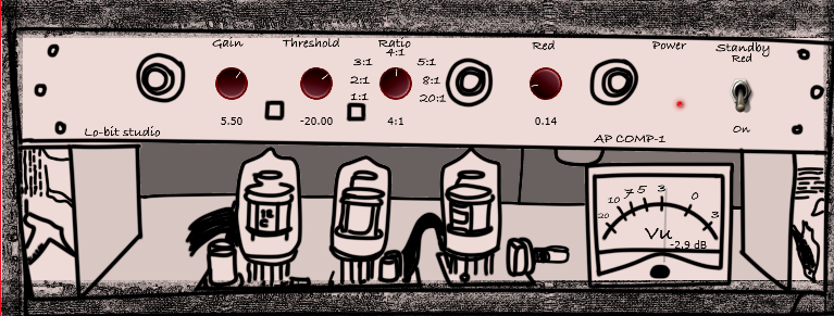
A compressor is far more than a utility for reducing dynamic range. The enduring relevance of legendary vintage compressors in contemporary recording studios lies fundamentally in their non-linear circuit responses and musically coherent harmonic generation.
In this article, we examine the electro-acoustic architecture of two defining hardware units: the Teletronix LA-3A optical leveler and the British Pye PWM/VCA compressor. We will also discuss how fusing these distinct architectures in digital signal processing (the design core behind AP COMP1) solves practical mixing dilemmas.
1. Teletronix LA-3A: Electroluminescent Memory and CdS Photocells
Introduced in 1969 as a solid-state successor to the tube-based LA-2A, the LA-3A retained the core component that defines classic optical compression: the T4B optical attenuator.
The T4B module pairs an electroluminescent (EL) light panel with cadmium-sulfide (CdS) photo-conductive cells. Gain reduction operates via a physical light-to-resistance conversion:
[Audio Input] ──> [EL Panel (Light Intensity)] ──> [CdS Photocell (Variable Resistance)] ──> [Gain Attenuation]
Mathematical Modeling of Multi-Stage Release
The defining acoustic trait of the CdS cell is its photoconductive memory effect: the decay time is directly dependent on the duration and intensity of the preceding light exposure.
- Initial Fast Recovery: In the first ~60 milliseconds after signal peaks subside, approximately 50% of the gain reduction recovers rapidly.
- Prolonged Tail Decay: The remaining 50% returns asymptotically over a period spanning 0.5 to several seconds, dictated by signal history.
This multi-stage release allows the LA-3A to clamp down swiftly on vocal plosives without producing unnatural pumping artifacts during sustained passages. It is why engineers describe optical compression as “gluing” vocals naturally into an instrumental mix.
2. British Pye Compressor: Extreme Transient Bite via Pulse Width Modulation
In contrast to optical leveling, the Pye 4060 compressor—a staple of London’s Olympic Studios that shaped the legendary drum sounds of Led Zeppelin and The Rolling Stones—employed a radically different gain reduction scheme: 250kHz Pulse Width Modulation (PWM).
Rather than relying on variable-mu tubes or field-effect transistors (FETs), the Pye circuit modulated the duty cycle of a high-frequency square wave carrier in proportion to the audio envelope, effectively chopping the audio at supersonic speeds to attenuate level.
Acoustic Consequences of PWM Architecture
- Incredible Attack Velocity: Transients are caught with zero overshoot, compressing early strikes into tight, punchy impacts.
- Aggressive Harmonic Edge: The high-speed switching imparts subtle odd-harmonic distortion that gives snare drums and percussion an unmistakable forward crack.
3. The Need for an Optical & PWM Hybrid Architecture
Modern mix workflows frequently encounter a tradeoff between these topologies:
- LA-3A Alone: Superb on vocals and acoustic instruments, but often softens the sharp percussive bite of modern rock drums or aggressive bass lines.
- Pye Alone: Phenomenal on drum transients, but its fast, decisive release can cause disjointed fluttering on dynamic lead elements.
By designing a DSP engine that models both the smooth, multi-stage optical envelope and the snappy British VCA transient response, mixers can blend or cross-modulate between transparency and punch in a single pass.
4. Discrete Low-Mid Harmonic Saturation (The RED Circuit)
A frequent drawback of in-the-box mixing is loss of body: when gain staging conservatively to avoid inter-sample overs, digital tracks can feel thin in the low-midrange.
The human ear perceives weight and punch predominantly in the 200Hz to 500Hz region. Applying standard parametric EQ boosts here frequently introduces muddiness.
To address this, the RED saturation circuit isolates the 200Hz–500Hz band and routes it through a non-linear transfer function modeling discrete silicon transistor saturation:
$$y = \frac{2}{\pi} \arctan(k \cdot x) + \alpha \cdot x^2$$
By increasing harmonic density rather than raw amplitude, mix elements project forward without clashing with the foundational fundamental frequencies of the kick and sub-bass.
5. Recommended Studio Settings
| Track | Configuration | Purpose |
|---|---|---|
| Lead Vocal | Mode: LA-3A, Reduction: 3–4dB, RED: +2dB | Leveling sustained phrases transparently while adding chest resonance |
| Snare Drum | Mode: Pye, Reduction: 4–6dB, RED: +3.5dB | Maximizing initial crack and bringing out the body of the drum shell |
| Drum Bus | Mode: Hybrid (50/50), Reduction: 2–3dB | Gluing overheads and room mics while preserving kick punch |
| Bass Guitar | Mode: LA-3A, Reduction: 5–7dB, RED: +1dB | Solidifying dynamic consistency across all fretboard registers |
*Tracks created using the environments, gear, and techniques featured on this site are available for preview and free download in the Lo-bit LAB Free BGM Library. Continuously updated.*

Lin Wolinski / Lo-bit record
Musician, Recording & Mixing Engineer, Music Instructor (Guitar, Bass, DTM, Composition & Arrangement), and C++ Audio DSP Plugin Developer.
Active as Bassist, Synthesist, Backing Vocalist, and Composer/Arranger for the rock band "Once Grace Forever".
Following musical study in Australia, actively engaged in professional music production, bespoke mixing & mastering, boutique audio plugin development under "Lo-bit record", releasing royalty-free music assets, and authoring audio engineering resources.